Page 8 of 9
Re: Robsey's Thread of Random Ramblings.
Posted: Sun Jun 18, 2023 5:06 pm
by Robsey
Two issues had cropped-up.
1 - I had initially got confused between 'early' and 'late' temperature sensors. My prior successful gauge / sender tests were carried out on a 'later' sender.
Recent tests with an 'early' sender fitted to my original thermostat housing was a mile out.
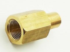
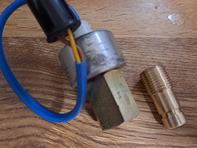
The only solution is to fit an M10 to 5/8 unf adapter and fit a Maestro sender.
2 - Speed pulse.
I knew historically that the Rover 800 pulse unit used 4 pulses per revolution.
I needed 8 per rev.
The maths is quite boring, but the exact figure is approx 7.67 pulses per rev. So 8 is near enough.
I tried a pulse pick-up
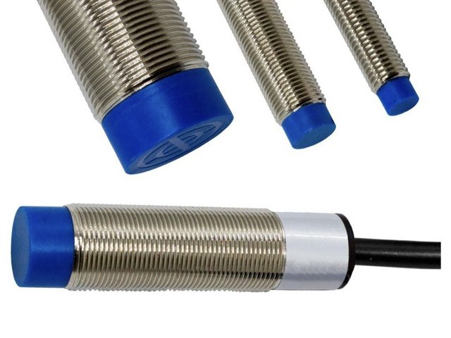
and an 8 pole rotor plate. - seen here spinning in a lathe.

Sadly no dice...

Re: Robsey's Thread of Random Ramblings.
Posted: Sun Jun 18, 2023 5:15 pm
by Robsey
Anyway - a very learned friend on the VW forum mentioned similar tests he'd tried on an abandoned Range Rover speedo cluster project.
He confirmed the 8 pulses per rev figure.
A few times he mentioned the Rover SD1 speed transducer.
Eventually I bit the bullet and bought a new-old-stock auto,box transducer.
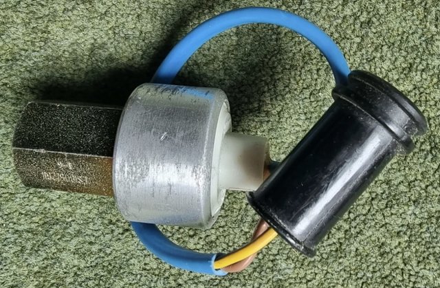
I was concerned about the output voltage...
The original Austin Rover documentation says...
6.5 v peak (air-gap) and 1.2 v reference (signal chopped by rotor).
I looked into voltage dividers and Schmitt triggers and all sorts of crazy electronic circuits.
My brain was fried. :/
So far, still no success.
Re: Robsey's Thread of Random Ramblings.
Posted: Sun Jun 18, 2023 5:18 pm
by Robsey
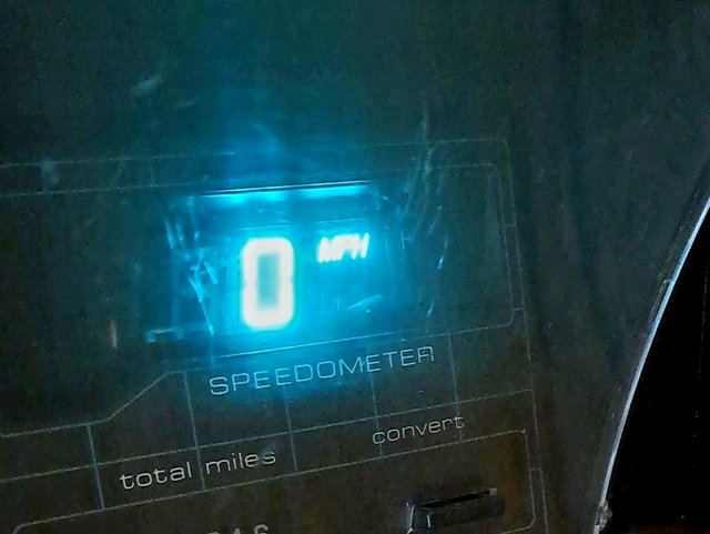
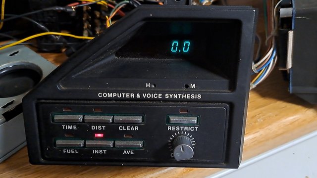
I dug out the dash again this morning,
along with my cordless drill.
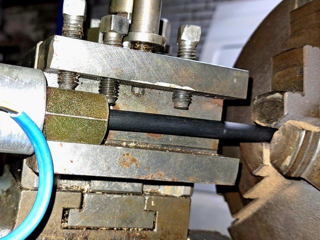
Using a piece of 3mm bore vacuum hose in the chuck to drive the transducer's 2.6mm square drive.
I squeezed the trigger, and the speedometer jumped into life.

Whoo hoo....

My initial failure was because I could not turn the drive quick enough by hand.
And highly unlikely in a T3 van...
Apologies for the mucky dash screen.
Re: Robsey's Thread of Random Ramblings.
Posted: Mon Jun 19, 2023 9:40 am
by vexorg
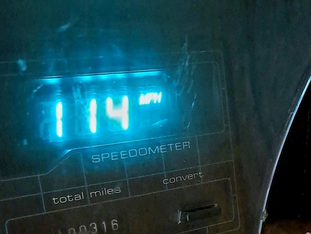
How high will it go, not sure 114mph will be enough for it

Re: Robsey's Thread of Random Ramblings.
Posted: Mon Jun 19, 2023 2:19 pm
by Robsey
The speedometer will go as high as 288mph,
but I doubt a 1980s 1.3 ton rectangular steel box will go much above 65mph.
Re: Robsey's Thread of Random Ramblings.
Posted: Sat Jun 24, 2023 11:48 pm
by Robsey
We had some lathe action tonight.
Wired up the PC power supply.
It looks like a mass of spaghetti, but it is quite safe.
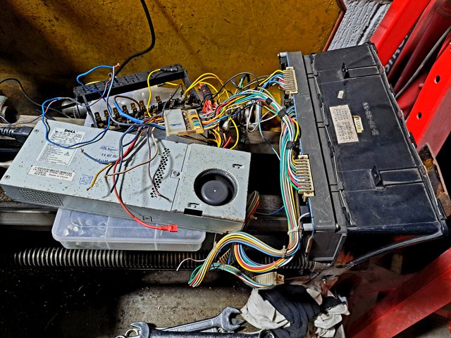
I then put the transducer into the tool holder, and linked the transducer spindle to the chuck using the 3mm bore vacuum pipe.
Powered it all up and tested the speedometer at the eight spindle speeds.
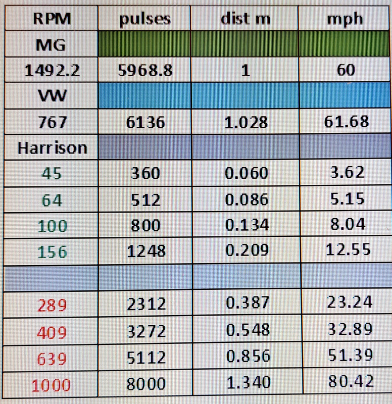
Results were very impressive - very close to my calculated speeds in the table from earlier this month.
Most speeds fluctuated but only by 1mph.
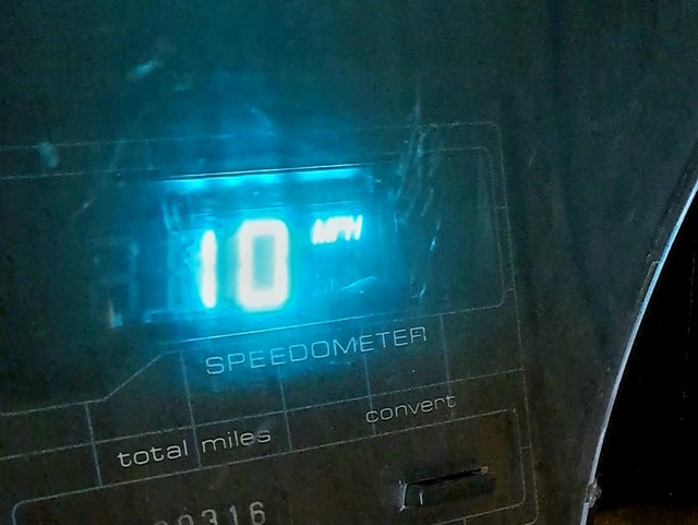
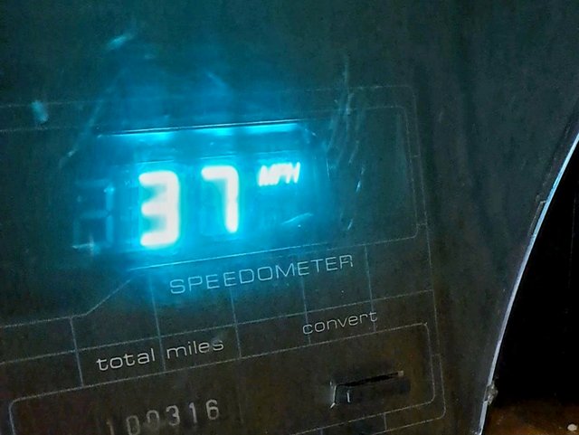
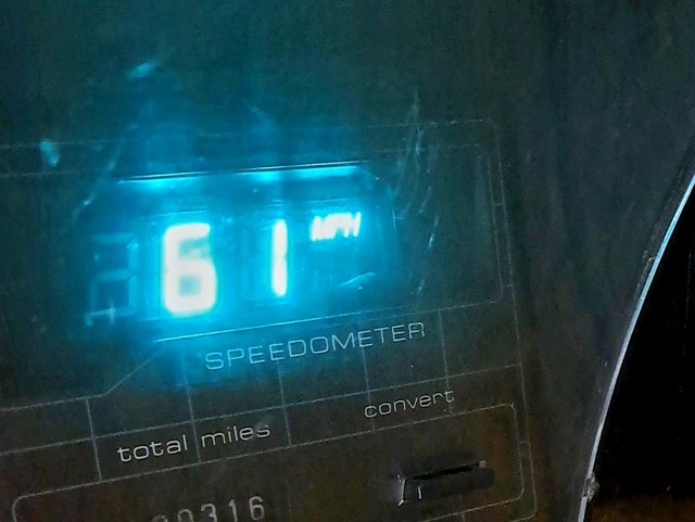
1 ) - 45rpm - Est = 3.62 - Actual = 0 (too slow to register)
2 ) - 64rpm - Est = 5.15 - Actual = 5 / 6.
3 ) - 100rpm - Est = 8.04 - Actual = 8 / 9.
4 ) - 156rpm - Est = 12.55 - Actual = 13 / 14
5 ) - 289rpm - Est = 23.24 - Actual = 23 / 24.
6 ) - 409rpm - Est = 32.89 - Actual = 33 / 34.
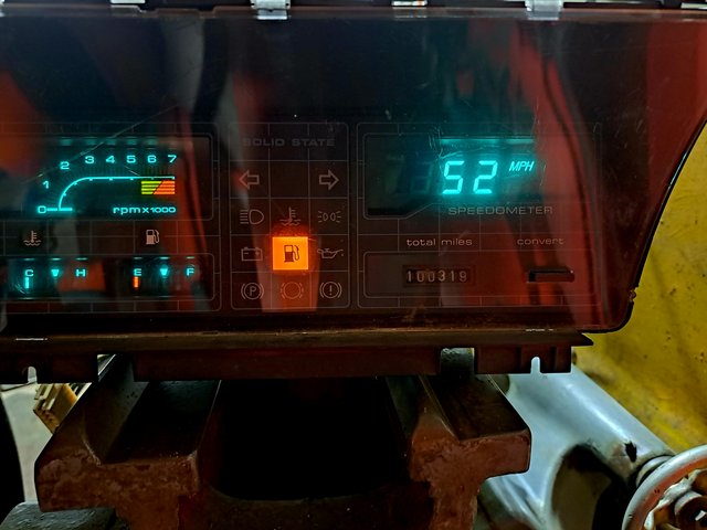
7 ) - 639rpm - Est = 51.39 - Actual = 52 / 53.
(See photo above).
8 ) - 1000rpm - Est = 80.42 - Actual = 77 (?)
That had me a bit puzzled...
Table from 3 weeks ago.
Re: Robsey's Thread of Random Ramblings.
Posted: Thu Jun 29, 2023 1:55 pm
by Robsey
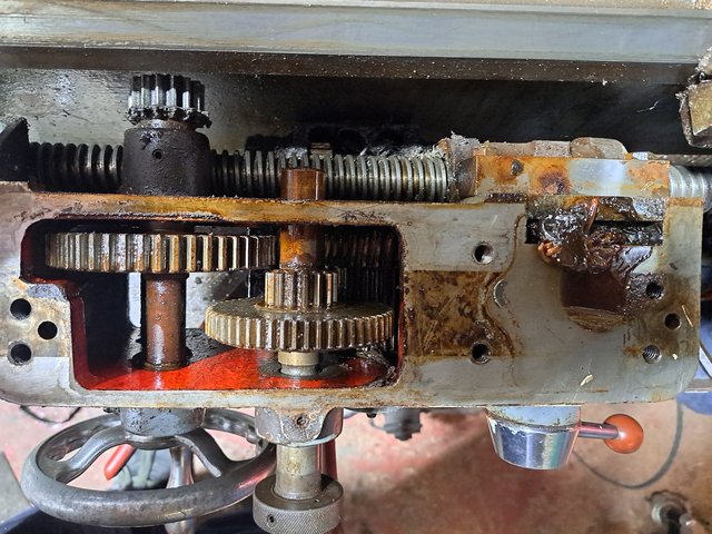
On Tuesday, I put my 1985 apprentice head on and did some 'proper' engineering.
I stripped, cleaned, refitted and adjusted the gear selection linkages and the clutch / brake assembly on the Harrison lathe.
The clutch arm had a huge arc of operation, instead of about 45°.
And the brake was all but non-existant.
Two hours later, the gearbox levers are still very notchy, but I presume that is just how they are with a crude interlock cut out in the linkage brackets.
But the clutch is now much more positive, and the brakes do stop the chuck a lot quicker.. .
Next job will be the saddle and lead-screw, so that I can get the screw-cutting function to work.
Re: Robsey's Thread of Random Ramblings.
Posted: Sat Jul 01, 2023 1:45 am
by Robsey
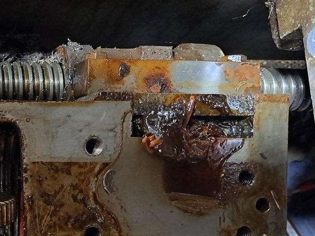
After repairing Troy's lathe...
It was full of swarf in the feed / traverse gearbox.
A good clean out and lube soon got the feeds etc working properly.
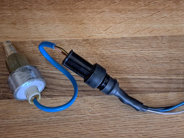
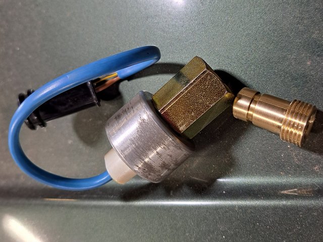
... I finished cutting the thread for the speed transducer adapter.
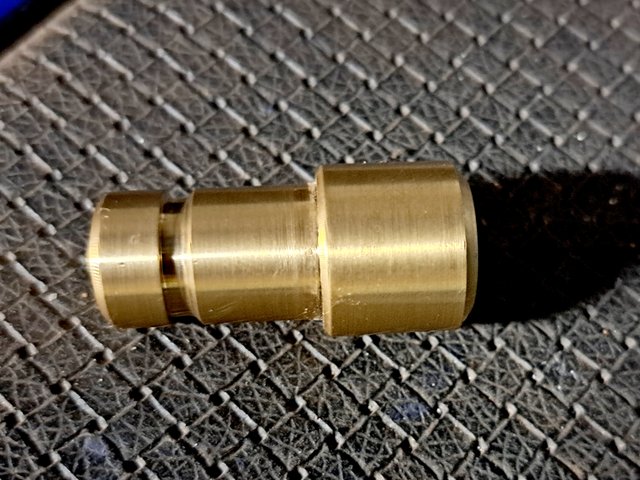
I may shorten the threaded part by approx. 5mm so that it looks tidier.
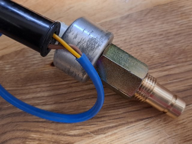
All it needs now is a 3D printed square-drive shaft link-rod.
As soon as I get a speedo cable and measure the drive-cable size at the dash plug end.
Re: Robsey's Thread of Random Ramblings.
Posted: Sat Jul 01, 2023 1:48 am
by Robsey
Also for good measure -
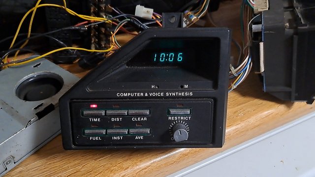
I replaced the LED clock circuitry in the Alfasud clock assembly, and mounted it in the ashtray adaptor for the camper van.
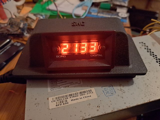
It also doubles up as a voltage meter 8)
Re: Robsey's Thread of Random Ramblings.
Posted: Sat Jul 01, 2023 9:04 am
by Robsey
As an update, I have managed to find a source for the voice unit for the maestro.
I also have an SD1 fuel flow transducer, so I 'may' be able to get the whole thing up and running properly, including the audible voice warnings.
The SD1 does appear to share the same wiring conventions as the Maestro, albeit a few wire colour differences.
Re: Robsey's Thread of Random Ramblings.
Posted: Sat Jul 01, 2023 4:43 pm
by 3cav3
I always used to be fascinated with the talking dash when I was younger, guess it reminded me of kitt, lol.
Re: Robsey's Thread of Random Ramblings.
Posted: Sat Jul 01, 2023 5:26 pm
by Robsey
I can see it being a 'fun' gimick at first, but I am sure that it wouldn't take long before I would be turning the audible-warning volume off.
Amazingly the wife is totally unaware of my antics, or that I even have the digital dash - despite the dash being in a box in the kitchen.
I could understand if I was doing my experiments in the unit 6 1/2 miles away. - but she is never more that 20 feet away from it - lol
Re: Robsey's Thread of Random Ramblings.
Posted: Sun Jul 02, 2023 3:04 am
by ilovedmymantas
Nice lathe work. I miss my engineering apprenticeship days, creating something from nothing with 1-2 thou tolerances. Happy times
First rule of apprentice school- always check the oily coolant nozzle isn't directed towards you when you switch the power on

Robsey wrote: ↑Sat Jul 01, 2023 5:26 pm
I can see it being a 'fun' gimick at first, but I am sure that it wouldn't take long before I would be turning the audible-warning volume off.
Amazingly the wife is totally unaware of my antics, or that I even have the digital dash - despite the dash being in a box in the kitchen.
I could understand if I was doing my experiments in the unit 6 1/2 miles away. - but she is never more that 20 feet away from it - lol
I'd be the same but at least there's an off switch

. Perhaps you could loop the warnings for shows?
I think i'd describe my missus as oblivious, she wants to be driven everywhere but the eyes glaze over as soon as a problem occurs and I want to explain it to her

Re: Robsey's Thread of Random Ramblings.
Posted: Sun Jul 02, 2023 11:27 am
by Robsey
Oh lordy yes.
Apprenticeship days...
My training was done at Ferranti PLC via a Youth Training Scheme. (1984 / 1985).
Anyone else old enough to remember those in the 80's.?
Our first lathe rule was do not leave the chuck key in the chuck.
Followed by no long sleeves, no ties, and no hippy-colars or anything else that you could get sucked into the machine by.
------
My thought is -
Respect anything that could rip your arm off in a heartbeat.
-------
All we need now, is a nice simple milling machine, dividing head, and a few other useful accessories.
Re: Robsey's Thread of Random Ramblings.
Posted: Sun Jul 02, 2023 2:07 pm
by Robsey
Now that I have done the theory...
I ordered the correct 'Rists' connector complete with pins and rubber seals.
Despite being very dated looking, these connectors from the 70s and 80s are still available on line.
But amazingly not from Rimmer's.
45cm (18") long cable tails should be enough to join into the main dash loom.
-----------------------------
Moving onwards...
Flushed with excitement of the dash functions now working, I have elected to look at adding the voice unit too.
One thing that always fails on the MG fuel computer is the fuel flow transducer.
However hoping that the SD1 will be a suitable for other parts, I have bought the SD1 fuel flow transducer.

I am sure that I read, that it reads the amount of fuel flowing to injector No.8.
Again, using an 8 vane hall sensor for an output signal.

My theory tells me that the eight vanes multiply the output signal by eight. One for each SD1 3500 cylinder.
With the van being a 4-pot beastie, the fuel computer may say that I am using twice as much fuel than I am in reality.
------------------
I have bought an SD1 manual on pdf, so that I can zoom in and make it easier on my tired eyesight.
I struggle with hard-copy wiring diagrams these days.
Re: Robsey's Thread of Random Ramblings.
Posted: Mon Jul 03, 2023 9:43 am
by vexorg
I'm not sure you can equate fuel flow directly to the number of cyinders like that. Will be a simple cc/min value
Re: Robsey's Thread of Random Ramblings.
Posted: Mon Jul 03, 2023 12:40 pm
by Robsey
I am certain you are right.
Who knows with the 70s /80s production methods, quality and designs from Austin / Rover / BL.
I suspect it will probably be perfectly okay.
More by luck than judgement.
Re: Robsey's Thread of Random Ramblings.
Posted: Sun Jul 09, 2023 4:45 pm
by Robsey
I bought a CD with the SD1 factory workshop manual on it, so that I could ensure that all the wiring was correct.
Unfortunately it was a very early manual. Upto 1979.
There was no mention of any other transducer except the hall effect camshaft position transducer.
So that was a waste.
Never mind... I think the wire colours 'sort of' match.
Back in the box for now.
I need to find someone with the manual for the later models. (Ideally 1984 to 1987)
--‐-------------------------
I have shortened the speedometer adapter to make it look tidier.
‐-------------‐--------------
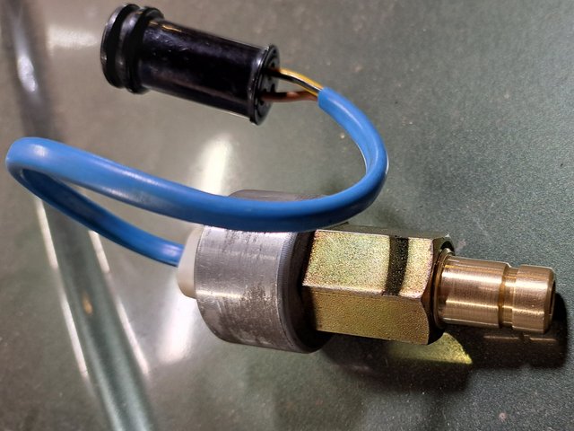
I plan to make the coolant sensor adapter next week.
Re: Robsey's Thread of Random Ramblings.
Posted: Sun Jul 09, 2023 9:01 pm
by 3cav3
On youtube there's someone called James who's channel is called Nitrosilva, he's almost guaranteed to have a manual as he's mega big into SD1s.
Re: Robsey's Thread of Random Ramblings.
Posted: Sun Jul 09, 2023 10:06 pm
by Robsey
Cheers fella,
Looks like a possible lead.
I see there are lots of videos about SD1's.
But it looks like he does not have the later electrics fitted.
I will send him a message.
Re: Robsey's Thread of Random Ramblings.
Posted: Mon Jul 10, 2023 9:01 am
by 3cav3
I know he's totally rebuilt a D plate ex police SD1 including the electrics so hopefully he can help. It was the one featured a few months ago on car SOS.
Re: Robsey's Thread of Random Ramblings.
Posted: Tue Jul 11, 2023 5:54 pm
by chrisp
"Our first lathe rule was do not leave the chuck key in the chuck"
Ah yes, I remember doing just that on the lathe in my school metalwork workshop. The chuck key shot out, narrowly missing me and landed some distance away, luckily not hitting anything or anyone in the process.
The whole class was then ordered to gather round me and the lathe for a "learning point" from the teacher, and I was duly chastised. I didn't make that mistake again!
Re: Robsey's Thread of Random Ramblings.
Posted: Sat Jul 15, 2023 11:58 pm
by Robsey
After a crappy week at work, there was only one thing to do.
Tidy up and sort a few connections on the adapter loom.
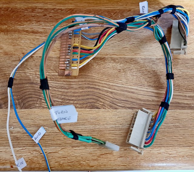
Not many wires to do now.
White wire - for the instrument dimmer rheostat.
Blue / yellow - for the brake fluid light
Blue for the speedometer pulse in.
I have a white wire on VW connector pin T14 / 14, which is for the blank green "spare" on the dash.
I may use this for the cruise control... don't know yet.
Re: Robsey's Thread of Random Ramblings.
Posted: Sat Jul 22, 2023 12:58 am
by Robsey
I thought that I had written this post already, but apparently not.
A new (for me) toy arrived on Tuesday, care of a good friend on the VW van forum.
He had seen my digi-dash thread, and fancied having a go using a GPS Arduino set up to create speed pulses.
Anyway his dash came with the fuel computer voice unit, which he had no plans to connect up.
So for a modest price, I was able to tease it from his ownership..
So far I have not had time to wire it up.
Pesky work getting in the way.
With VBOA tomorrow, I will have to wait until Sunday before I can try to get it talking to me.
I have ordered the correct 5-pin and 9-pin Rists connectors to build up the final part of the jigsaw.
The 9-pin arrived today.
The 5-pin is due early next week.

I still have all of my wiring tables from 2020, so we should be good to go.
Re: Robsey's Thread of Random Ramblings.
Posted: Sun Jul 23, 2023 11:03 am
by Robsey
She Speaks....
I wired up a "period" Philips speaker originally fitted to one of the late father in law's vehicles back in the 80s.
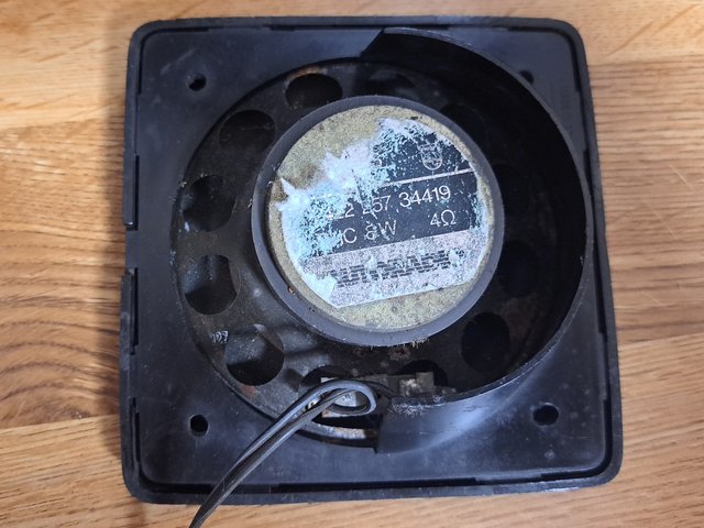
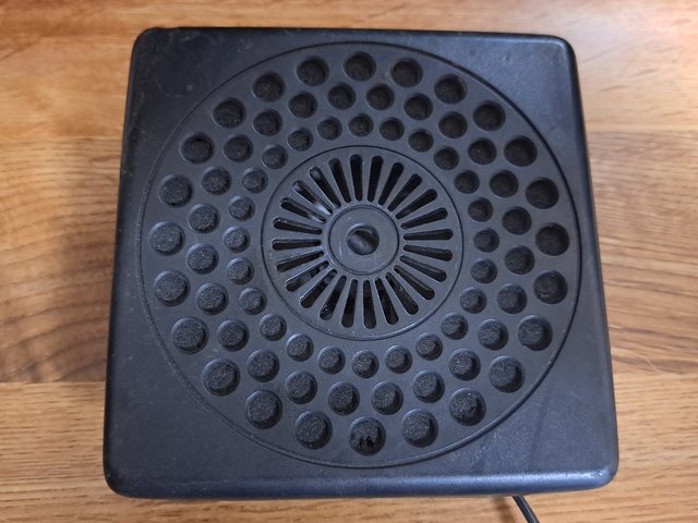
I thought that I should go for the original naff 80s sound.
Aside from a few niggles, the fuel computer voices work in good old yesteryear fuzziness style.
I will put a couple of videos up, when I can locate my account / channel details.
The other thing I failed to notice until I played back the video, was that my tired ten year old Samsung washing machine was churning away behind me.
Oopsies - lol.
https://youtu.be/RRvski1hZRE
https://youtu.be/sZs94uG4odg
For info -
Speaker wiring is a doddle, but totally against normal convention.
Speaker '+' to either the green or black wire in the two-pin connector.
Both if using two speakers.
Speaker '-' direct to ground / chassis.
This is where I mean '
against normal convention'.